|

|
 |
Stereoscopic
Matchmove/Layout
for Journey To The Center Of The
Earth - 3D, using 3D Equalizer
and Maya [12/12/07]
Author:
Michael Karp, SOC
|
|
|
In 2007, I
worked as one of the match move/layout
supervisors on the first digital
stereoscopic feature film, Journey
To The Center Of The Earth -3D.
I would like to share my experiences
from this production, especially
concerning the use of 3D Equalizer and
Maya for stereoscopic work.
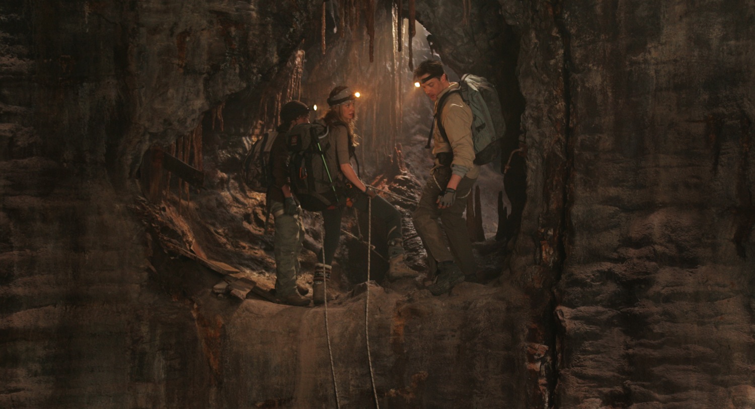
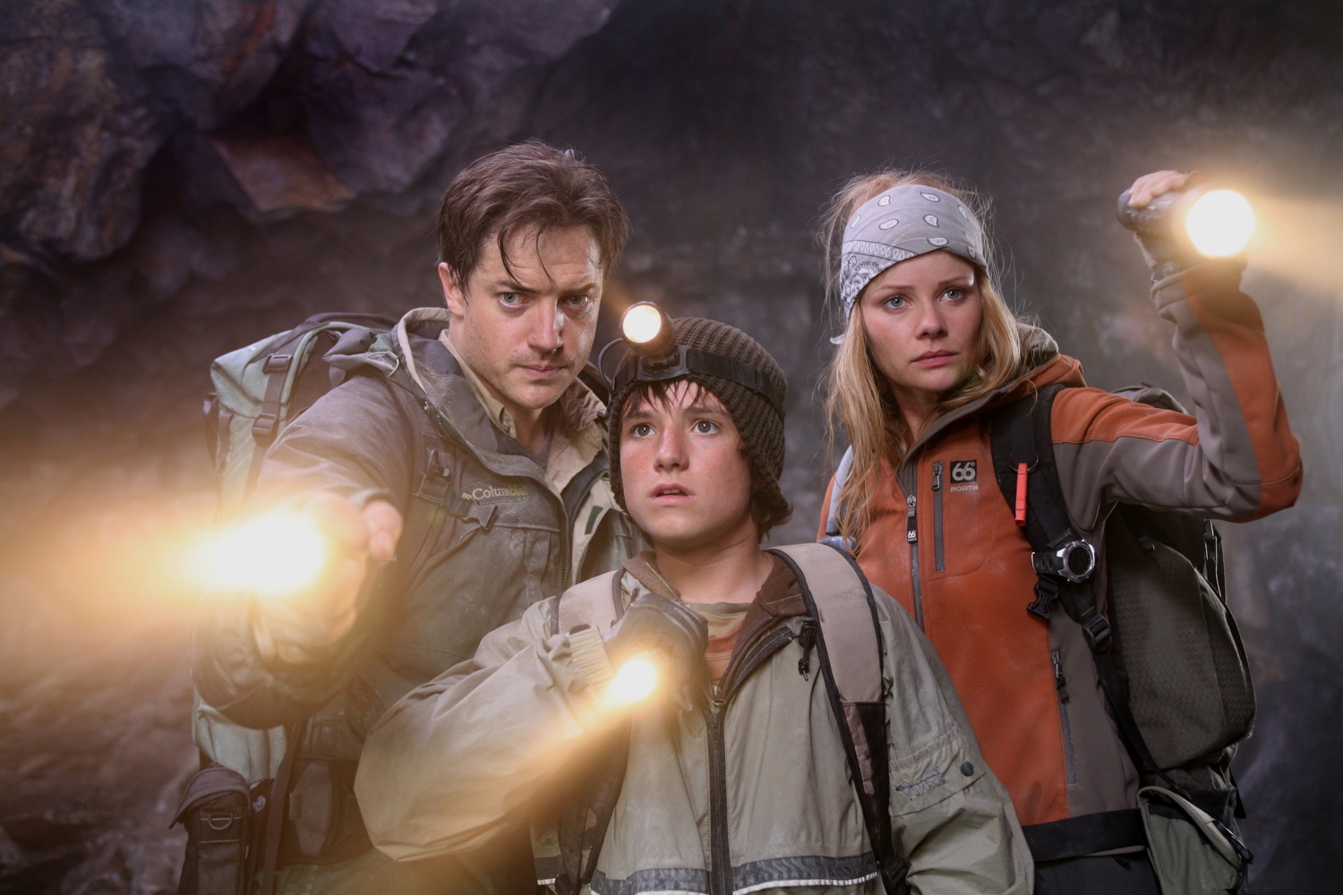
JCE (Journey Center
Earth) was produced by Walden
Media, directed by Eric Brevig,
photographed by Chuck Shuman and stars
Brendan Fraser. Principal photography
and visual effects work was primarily
produced in Montreal. The overall vfx
supervisor was Chris Townsend and the
vfx supervisor for Meteor Studios was
Bret St. Clair. Other important vfx
studios also did considerable work on
JCE.
Previously, I had worked on other
stereoscopic films, including the 65mm
productions The Ant Bully - 3D
(Imax) and T2-3D (5-perf). Ant
Bully was pure CGI animation and
so the stereoscopic problems were very
different than a live action visual
effects film like JCE.
|
|
|
|
|
JCE
was photographed with the Pace stereo camera,
the design of which was commissioned by James
Cameron. The Pace design utilizes two Sony
HiDef 24P cameras looking into a beam
splitter. These video cameras are relatively
compact, since they consist only of a
lens/image sensor and no tape, disc or other
recording device. A standard camcorder
contains an integral recorder, but in our
application, only the camera was on stage and
the MPEG4 recorders were far away, in a high
tech video village. Traditional 35mm or
65mm stereo cameras using an outboard beam
splitter can be very large, especially in the
case of the twin 65mm Showscan/Panavision
cameras that we used for Cameron's T2-3D.
By using compact "film look" video cameras,
the stereoscopic rig was brought down to a
relatively small size. Although beam splitter
stereo rigs are somewhat silly looking and
"Rube Goldbergish", they are often considered
the most artistically flexible rig type.
The Pace stereo camera is typically fitted
with matching, synchronized zoom lenses on the
two stereo camera heads. On any stereo show,
the critical stereoscopic settings are
interocular and convergence, which can be
changed dynamically during actual photography.
The animated focal length, convergence and
interocular values are recorded every frame
and then embedded in the 1920x1080 video
image. Various "single system" and "double
system" techniques can be used for
synchronizing this stereo meta data to the
image. A separate ASCII file can be used, or
in our case, stereo meta data was placed in
the .dpx header and in the EXIF section of our
.jpeg proxy images.
On JCE, Pace meta data, the i/o and
convergence was floating point and the focal
length was truncated to an integer. The
rounding down of the focal length value (no
fractions, just whole numbers) caused minor
problems and probably will be fixed in later
versions of the Pace stereo encoding software.
Interocular (i/o) is the distance between the
left and right eyes. In humans, this distance
is typically 2.5 inches, but artistic and
eyestrain considerations mean that the
photographed i/o may be set at many unusual
values and might even animate during the shot.
The greater the (tx) distance between the two
eyes, the stronger the stereo effect. But if
the effect is too strong, the human eye will
not be able to fuse the binocular images
together and painful eyestrain will result.
The stereo effect would be lost and the
viewers eyes would physically hurt.
Convergence is the pan angle between the two
stereo cameras. Imax films typically maintain
the left and right cameras as parallel to one
another, but many other stereo systems "toe
in" the cameras. This is a controversial and
subjective process, with different artistic
camps. What is important to the stereo
matchmover is that the convergence, i/o and
focal length of the original photography must
be determined so that when visual effects are
added to the plates, the stereo depth of the
CGI elements closely match the live action
elements.
The stereo meta data from the Pace camera is
very useful, but because it uses mechanical
encoders in the chaotic, real life field
conditions of Hollywood production, the data
will not be perfect. Typically, it need to be
trimmed in the matchmove/layout process. Much
more on that.
In the world of matchmove, it has become well
known that lens distortion must be compensated
for in demanding shots. This is especially
true for anamorphic lenses and zooms.
Anamorphic lenses typically display heavy
barrel distortion (where the corners of the
frame bow in), which in 3DE would be
a positive distortion value. JCE was
primarily shot with zoom lenses. At wide
angles, the JCE zoom had heavy pin
cushion distortion (where the corners of the
image bowed out), but as the lens
was zoomed to longer focal lengths, the
distortion reduced and became more neutral.
Because of the extensive use of the
Technocrane on JCE, none of our shots
involved actual zooming and the zoom lenses
were merely used as variable primes. 3DE does
possess strong tools for calculating zooming
shots, but these situations are often very
challenging, especially if the camera also
translates.
On large productions, it is common to
photograph lens distortion grid charts at
multiple focal lengths. 3DE can attempt to
automatically determine lens distortion, but
distortion testing with grids can also be very
helpful.
In addition, zoom lenses often display
"mustache" distortion, where one part of the
image frame bows in and another region bows
out (barrel and pin cushion). These
distortions are more difficult to correct.
When barrel distortion is corrected for in a
matchmove system, many of the pixels at the
edge of frame may be pushed outside of the
frame, truncated and lost. There are different
methods of dealing with this. Some processes
will make the undistorted frame larger (past
2K) and other systems will maintain the pixel
position at the edges of the frame the same
and offset the more central pixels. On JCE,
we added a 25% border to every plate before we
matchmoved. Later, the lighting department
redistorted their renders and the composite
department then cropped back to 1920x1080 in
the final stages.
|
|
Unified Solve vs. Meta
Data
|
When
matchmoving
stereo images, both the left and right eyes
must be tracked and they must be placed in
the same stereo space. Typically, the analog
encoder stereo meta data from the camera rig
is not accurate enough for demanding shots
such as set extensions. This is not a
criticism of the Pace Camera system. After
spending many years operating motion control
systems, it became obvious that mechanically
measuring the exact sub-pixel position of
cameras and optics (outside of laboratory
conditions) is almost impossible on a film
set. The stereo meta data from the Pace
camera will get you close to an accurate
stereo reading, but only stereoscopic
matchmove will provide an exact result.
|
|
|
If
you attend a stereoscopic film (such as Beowulf),
you can do an experiment that will
illustrate some 3D principles.
First, remove the 3D glasses from your
face. Observe that the stereo effect is
caused by the fact that closer objects will
display more left right separation on the
screen and distant objects will be more
"converged". In Imax films, objects at
infinity will typically have no divergence
and closer objects will diverge. But in
other systems, the stereographer will often
pan the left and right cameras towards one
another minutely, changing the convergence
point by using camera toe-in (ry). In this
case, both near and far stereo objects will
diverge and only a mid point will converge.
A small adjustment of the pan angle between
the two cameras has a large visual effect on
the audience. On a 2k image, the near
objects can have no more than 80 pixels of
stereo shift and the distant objects can
have no more than about 30 pixels of
negative shift (wall-eye). The human eye
will tolerate more stereo separation for
near objects (80 pixels) than for distant
objects (30 pixels). This is because the
human eye muscles are built to pan towards
one another, but not to pan away from one
another (wall eye). These pixel separation
limits (80 hither, 30 yon) are subjective,
approximate and depend on projection
techniques, choreography and editorial
style.
A surprisingly large amount of vibration
between the left and right cameras can exist
and the stereoscopic images can still easily
be fused by the human eye. For example, on T2-3D,
our twin 65mm stereo cameras were placed on
a camera car driving on rough terrain.
Because of the cantilever design, the two
cameras would shake against one another. If
you removed your stereo polarizing glasses
in the theater, the vibration between the
two images was disturbing. But when you put
your stereo glasses back on, your eye fuses
the images perfectly and the unsteadiness
between the stereo images disappears. But if
we are talking about a match move vfx shot,
then the vibration between the two eyes will
not be accurately recorded in the meta data
and Unified Solve may be necessary to
converge the left and right match moves
properly. Even though the Pace stereo camera
is a low vibration design, mechanical and
optical inconsistencies between the
left/right optics can show up as the lens is
rack focused, etc.
The job of the stereo match mover is to
figure out what the convergence and
interocular of the original camera was set
at. As mentioned, for critical shots like
set extensions, the encoder data will not be
good enough and unified solve (to be defined
shortly) is needed.
FYI the human eye can easily see a half
pixel shift in stereo placement. I will give
an example from Ant Bully - 3D. A
typical shot would be of an ant walking on
the ground, ant and ground elements rendered
in different passes and then combined in
Nuke. But the uneven terrain was rendered
with displacement mapping, which meant that
the original smooth, flat ground plane
geometry that the character animator
originally walked her ant over is now bumpy.
The rendered ground then had variegated
height that the character animator could not
anticipate. In monoscopic, this is not a
problem, but in stereoscopic, the CGI ant
would often appear to either float above the
dirt or to have her feet buried in the dirt.
It is generally only practical to fine tune
this fix in the final 2D comp, not in the
eariler Houdini or Renderman stage. And we
found that the eye could sense a stereo
mismatch of as little as half a pixel (at
2K).
The important point is that for critical
shots, the left and right eyes must be match
moved in depth precisely to one
another. Many of the JCE shots
involved actors floating in air and so their
feet would not actually touch the CG set. In
this less demanding situation, the stereo
meta data from the Pace camera was good
enough, after a simple trim in the Maya
camera. But when the live action feet are
touching the CGI or there is a set
extension, then the more accurate Unified
Solve is used.
When using meta data, only the right eye is
matchmoved and the left eye transform is
sent to Maya from the camera encoders. But
in Unified Solve, both eyes are matchmoved
together and the left and right camera
solves "talk" to one another inside of 3DE.
Unified Solve is basically bringing both the
left and right plates into 3D Equalizer and
tracking a percentage of identical features
for both eyes. Unified Solve is especially
easy with blue screen markers, since 3DE
Marker mode finds the exact center of the
dot pretty accurately for both eyes. Finding
the same center of the marker for both eyes
is important, so that in stereo the
resulting matchmove of the blue screen
doesn't float in front or behind the correct
stereo depth.
On JCE, wind machines often blew the blue
screen markers around, so the 3DE
translation smoothing value was increased to
avoid a noisy motion solve.
In other JCE shots, the actors would
walk on rocks. These features require
Pattern Tracking (not Marker Tracking) and
it requires more human intervention to
insure that the feature is tracked for
exactly the same spot in the left and right
eyes.
Because earlier versions of 3DE already
supported using multiple plates and cameras,
Unified Stereo Solve has always been a
standard feature in 3DE. Unified Stereo
Solve is just a nickname for an already
existing capability. Nevertheless, special
3DE stereo constraint features were created
by Rolf and Uwe to enhance Unified Solve.
When using Unified Stereo Solve, you can
combine the Autotracker with manually
created tracks. A certain number of common
left/right points will need to be tracked
with user intervention. This will ensure
that the feature is the exact same spot on
the set for the left and right eyes. The
remainder of the tracks do not need to be
common between the left/right eyes and you
could optionally use the autotracker.
As mentioned, Unified Stereo Solve is almost
always necessary on stereo set extensions
since meta data will rarely be perfect
enough. You can trim the encoder meta data
in Maya, but you can almost never get
all of the features in the eyes lined up
without Unified Solve. You could use a
"least square fit" (LSF) surveyed solver
like rasTrack to improve the meta data for
the secondary eye (left, usually), but the
3DE Unified Stereo Solve is ultimately the
easy and elegant method.
It is well known that surveyless matchmove
does not always create plausible solves.
Sometimes you end up with a calculation that
looks like an M.C. Escher painting, lovely
in 2D, but ludicrously impossible in 3D
space. Typically a 3DE user will use
Reference Frames to add parallax and solve
this problem. Similarly, Unified Stereo
Solve may not always provide plausible
stereo solves. For this reason, 3DE added
stereo constraints. Theoretically, the left
and right cameras should be exactly
left/right of one another and not at
different heights (local camera space) or
weird skew angles.
The 3DE stereo constraints ensure that only
the i/o (tx) and convergence (ry) between
the cameras can be different between the two
eyes. All other values (ty, tz, rx, rz) will
be constrained to zero.
On JCE, only the convergence was
animated on set. but other shows (like T2-3D
and Avatar) will have also have
animated i/o. 3DE will support this
technique in later releases. Animated i/o
will be read into 3DE, from an ascii file.
|
|
Trimming meta data
|
|
Many match moves cannot be solved
with Unified Solve and so meta data must be
used and then trimmed. In this mode, the user
match moves the master (usually right) eye and
then trims the left eye's meta data. Typically
there will be large errors to correct side to
side [Y convergence/pan/ry] and left right
interocular (tx). But there will also be
slight up-down stereo errors (rx,ty), which
also will need to be trimmed. Usually the trim
is in Maya, but occasionally the trim is done
2D in Shake. The trim may even need to be
animated on tricky shots.
Again, the important point here is that the
eye will tolerate fairly large stereo
convergence errors between the eyes, but when
you are matchmoving and compositing between
two eyes, then stereo errors must be fixed so
that the layered elements sit properly in
stereo depth.
In our system, as soon as the meta data was
read into Maya from the EXIF/JPEG file, the
meta data was baked. This is because the rgbA
premult image does not support EXIF meta data
(because it is TIFF, SGI, etc., not jpeg) and
we didn't want our meta data to disappear when
we switched from the blue screen plate to the
extracted blue screen premult plate.
When trimming meta data, you
typically trim the convergence first and the
interocular later. If you can find a point in
the image where the cameras converged, trim
the secondary (left) eye so that the tracking
marks line up in both eyes (at the mid
distance convergence point). Then, trim the
interocular. Typically during the i/o trim,
the near and far points for the left eye will
"swing and pivot". The far points (yonder of
convergence) will swing one way and the near
points (hither) will swing the other, all
pivoting around the convergence point. If you
don't trim the convergence first, you may need
to use more of a confusing trial and error
process to trim the meta data. Even if the
convergence is at infinity, it is probably
easier to start trimming with the convergence,
before i/o.
In Houdini and Maya, the view port
will optionally display an overlaid 12 field
chart. Since there are 24 horizontal grid
boxes, each grid box coincidentally occupies
80 pixels on HD (1920/24=80). This is
extremely convenient, since 80 pixels is the
exact maximum suggested value for the
foreground stereo divergence between the left
and right eyes. If you toggle the
Maya/Houdini/Shake view port between the left
and right eyes, you can easily see whether the
fg image is shifting more than one grid's
worth of offset (in Shake, we just took a bit
map image of the field chart from Maya and
added that rendered grid to the Shake
composite tree).
Many shots will need minor stereo
convergence fixes in the 2D stage (i.e.
Shake). In this case, the compositor may need
to zoom in slightly on the image, since HD
theoretically has no spare pixels on the left
or right and the 2D shift convergence fix will
reveal missing picture. This may not even be a
problem on a blue screen shot where the actors
don't touch the left or right frame line.
Some isolated shots may have so
much stereo eyestrain erroneously baked into
them by the original photography, that the
shot is unfixable. Cameron suggests showing
such a shot flat in monoscopic, using the
right eye image for the left as well. Another
possible solution is to take the right
monoscopic image and converting it to
stereoscopic. There are several companies that
specialize in the stereoscopic conversion
process and their proprietary technology and
patents vary widely from one another.
Certain stereo plates may look
good as far as eyestrain considerations go,
until the layout process reveals unanticipated
problems. Let's say that we have an actor in a
blue screen shot and he reaches his hand out
towards the camera. We know that the yonder
objects usually should have no more than -20
pixels of divergence and the hither objects
should have no more than +80 pixels of
divergence. But what if these conditions are
seemingly met, until a CGI background greater
in depth than the blue screen is added in
layout? And what if foreground particle
systems (dust, debris, rain, etc.) are added
to the composite or the actor is reaching out
to a down stage CGI element? Then we may
experience serious stereo eyestrain in the
composite, even though the original
photography was apparently fine. So we see
that the original photography will often need
stand in objects ("stuffies") on set to help
judge the final stereo effect.
|
|
3DE proxy image system
|
As you probably know, 3DE has a
terrific proxy system for image sequences.
Typically, the F5 button
is user assigned to bring up full res, the F6
button half res and the F7
button is quarter res. Great feature.
|
|
Object tracking in 3DE
Stereo
|
Often a Unified Stereo Solve
will work well without 3DE stereo
constraints, or sometimes will be superior.
Please experiment, matchmove is not an exact
science. Warning: Object tracks in 3DE may
not work properly without the 3DE stereo
constraints enabled and the object may
locate in different space left/right. This
is not a problem for camera solves and you
may even wish to solve a stereo object as a
camera track and then convert to object
motion in Maya.
Surveyless Object tracking is always
ambiguous when it comes to Scale. In 3DE,
you can track multiple moving Objects with
cameras. On JCE, we object tracked mine
cars. But were they miniature mine cars,
close to the camera, or giant mine cars, far
from the camera? The monoscopic layout
artist can make any subjective decision
about scale that she likes, but not so in
stereoscopic. Since there are stereo eyes
triangulating on the depth of the Object
track, the scale of the Object track becomes
more "objective". Once the i/o and the
convergence of a stereo camera are
calculated, the scale of an object must be
at a certain value. The vanishing points and
epipolars of stereo cameras demand
that the object have a certain scale.
By using the stereo constraints in 3DE
(instead of regular Unified Solve),
the Object track will appear correct
in both left and right Maya eyes.
|
|
Maya considerations for
stereo layout
|
|
Many stereo tools were created for
JCE in 3DE, Shake and Maya.
For example, 3DE warpdistort can be performed
completely in Shake, using a Shake node
created by Mark Visser of Meteor Studios
(available Open Source on the 3DE website).
A stereo camera in Maya was originally
designed by Eric Gervais-Despres.
https://www.geo-z.com/ericgd
Eric now makes a commercial
version available to the public.
|
|
|
Multiple stereo cameras and projectors were
used, with suitable naming conventions so
that the stereo tools would act on all of
the cameras and projectors in the Maya
scene.
A great feature in Shake and other comping
software is a hot key to toggle between two
images that need to be compared. In Shake,
the hot key is "1".
So in Maya, we reassigned the "one" key so
that the view port would also toggle between
the left and right stereo eyes. Very useful
for rapid A/B stereo comparisons.
(Download
Python script for Maya "1"
button hotkey)
https://michaelkarp.net/lr.zip
In 3DE and Maya Live, there is an Autocenter
tool that will keep the 2D or 3D feature
centered in the viewport. With a MEL script,
It is also possible to autocenter anything
in Maya. So we set it up so that when we
zoomed in the viewport, using the over scan,
that the left/right autocenter and over scan
were always synchronized.
Maya supports rgbA premult plates in the
image planes used in Playblasts. For stereo
blue screen work, I would suggest the use of
an image plane with the alpha channel
enabled. It can be very distracting to judge
the stereo effect on a move test with the
blue screen not extracted. The visual depth
cues are...weird.
So on JCE, we had three pairs of
image planes prewired, the rgb (with the
plate unaltered), rgbA premult (blue screen
extracted) and MayaLive rotoPlane for
subpixel accuracy and image caching. We
could easily toggle between the three image
planes. Typically, matchmove/layout artists
would submit two playblasts for dailies, one
optimized for tracking and the other for
layout. The tracking test would show the
original blue screen and markers and the
layout test would have the blue screen
removed by multiplication/extraction and
would be more "artistic".
Surprisingly, almost all matchmove tests for
Hollywood 2K feature films are rendered at
half res 1K, which is quite adequate for
most shots and allows major efficiency
increases over full res 2k tests.
It is often useful to adjust the Maya Image
plane depth, but mandatory for 2.5 D
"projector/card" shots. A premult Image
plane depth will generally be near the
camera and regular blue screen Image planes
will be set for a distant depth. For
projector/card shots where the camera
translates away from the projector, the
image plane depth should be animated so that
the image is near the position of the
critical of the action. The image plane
depth for projector shots will always be a
subjective compromise. For mine car shots,
the image plane depth of the actors was
placed at the front of the mine car, but in
other shots, the depth was placed on an
important actor.
|
Head
lite shots in stereo
|
There are many shots in JCE
of characters carrying flash lights. Often
times the beam was not bright enough in the
plate or there wasn't enough smoke on the
set for the beam to illuminate, so a
volumetric light pass would need to be
rendered. Beams require smoke or
particulates in the air to be visible, but
that smoke can interfere with the
photography and extraction of a blue screen.
So many JCE shots required beams to be
created in post and of course to be match
moved in stereoscopic.
We created special rigs in Maya for the
headlights. Using the plate for the right
eye (master), the user animates a locator in
Maya that matches up with the position of
the light. It is very useful if the
headlight locator is rigged as follows:
-
A null called
Scalar is created and made a child of
the right (master)
camera.
-
A headlight
locator is a child of Scalar
-
Looking through
the right camera, animate just the
(local) tx and ty of the headlight
locator, you can lock the tz at zero
-
After the right
eye headlight animation looks good, look
through the left Maya camera. The depth
of the locator will be wrong in the left
eye, so animate the uniform scale (XYZ)
of Scalar so that the depth from the
left eye is correct.
Notice that any adjustments to
the left eye will not change the right eye
at all. This is a huge time saving
technique. You can also 2D track in 3DE and
export the track to Maya with Export_Single_MM_PointsV1.3detcl.
This script creates a camera in Maya with a
locator that follows the 2D track from 3DE.
You can then constrain the 2D point Maya
camera Scene node to the right Maya camera.
Then, reparent (bake) the 2D locator so that
it is a child of Scalar. The 3DE 2D tracker
is not perfect, but overall is the best 2D
tracker GUI and engine available in any
2D or 3D package. So it is very convenient
to 2D track in 3DE and then export to Shake,
Maya, etc.
By Aim constraining the headlight locator to
the right camera, you keep the locator
"square" to the right eye.
After you animate the headlight translations
for the right eye and set the depth for the
left eye, then you can animate the
rotations. Create another locator
HeadlightRotate that is Point constrained to
the headlight locator and then animate only
the rotations of the HeadlightRotate node.
You can also constrain a cylinder to the
HeadlightRotate node, for visual reference
of the quality of the animation. Obviously
we created a script to automate the creation
of each headlight rig.
On one occasion, we needed a different
stereo camera for the headlight track than
we did for the set extension for the scene.
Because the moving headlight was on the
actors head and was distant from the
stationary set, the matchmove for the set
was only suitable for the set extension. In
this situation, we duplicated the main
matchmove camera and gave special trims so
that the headlights would track properly.
Since the headlights are much closer to the
camera than the set, any minute translation
errors on the main matchmove were magnified
when tracking the headlights.
|
|
Reparent/ Baking
|
It is common in matchmove to
take a Maya node and give it a new parent.
For example, an Object track could be
converted to a Camera Track, or vice versa.
A Maya node could be baked to a new parent,
so that the scene is cleaned up for
publishing to other departments. Maya
constraints and baking are used for this,
but we used an automated Reparent script to
greatly simplify this process, available
here. Be sure to hide the viewports when
running the script. It will speed up the
bake, since the image plane is not
needlessly read in:
https://michaelkarp.net/reparent.zip
|
|
Variable speed shots
|
Several shots needed on JCE
needed speed changes and time warps. There
are two basic approaches.
-
The time warp can
be rendered to the plate in Shake,
Combustion, etc. using Twixtor, etc. and
the rerendered plate can be matchmoved
-
The time warp can
be calculated in Shake, Combustion, but
the actual plate that is matchmoved is
not altered. Rather, the speed change is
exported to Maya as an ASCII file and
Maya simulates the speed change.
Tracking a time warped plate is
problematic. Time warp creates motion
artifacts that may be acceptable to the
audience, but confusing to matchmove
software. The same goes for 2D repos of
plates for matchmove. So we tracked clean
plates and then applied the time warp in
Maya, using a custom script. This way, the
time warp could be modified at any time and
we weren't locked into the original time
warp decisions. The time warp in Maya was
baked back into all of the Maya animation
and the final time warp (if different) could
be exported back to Shake in a simple ascii
file.
|
|
Projector shots and
corner pins
|
We had a large number of stereo
"projector shots". These were two and a half
D "card" shots.
-
The 3DE matchmove
was imported into Maya
-
The camera was
duplicated and called projector
-
Many elegant
schemes were used to offset the camera
from the projector, both for nodal pans
on the projector and other shots where
the camera translates away from the
projector.
The farther the camera
translates from the projector, the more
obvious the "cheat" becomes. You may need to
aim the projector image plane back at the
camera, so the image doesn't get too
squished or keystoned. The convergence may
need to be trimmed on these fancy projector
shots, so that the stereo depth stays
correct with the cheated perspective.
When doing a projector shot repo, the plate
needs to be rerendered. Either you can
rerender the plate in Renderman or you can
export a corner pin to Shake. Adapting a
corner pin script from HighEnd3D, we
exported the four corners of the image
planes into a Shake tracker script.
Automatic compensation was made for lens
distortion, time warps, image padding, etc.
|
|
"Stabilizing" projector
shots
|
|
|
|
Treadmill shots
|
Many JCE shots had actors walking on
treadmills. We would typically
matchmove the camera in 3DE and hand track
the treadmill Object motion in Maya. Next we
would reparent the camera to be a child of
the treadmill. Reparent is
completely different than
parenting, because the child node animation
is baked, so that it's position in world
space does not change. The final step is to
Mute the animation on the treadmill
Object tracking. By muting instead of
deleting the treadmill object tracking, the
artist can easily undo changes if necessary.
By this simple procedure, an object track is
easily converted to a camera track.
|
|
Triangulation scripts in
3DE
|
There
are two powerful new triangulation tcl
scripts from 3DE. These allow 3DE points
that won't solve Passive, to still be
passively calc'd in 3D space. One script is
intended for monoscopic and the other is for
stereoscopic.
|
|
Animating ik characters in
stereo
|
There are many shots in JCE
where ik human characters were matchmoved
over plates of live actors, in stereo. It is
typical in character matchmove to carefully
pose the ik model for the first frame
lineup. This is especially important in
stereo, because the character must be
correctly posed for both left and right
eyes. The most important point is that the
i/o and convergence for the camera should be
set so that it works well with the posed ik
character. The scale and posing of an ik
character in stereo must be precise and all
other layout and world space decisions must
follow downstream from this first and
demanding step.
|
|
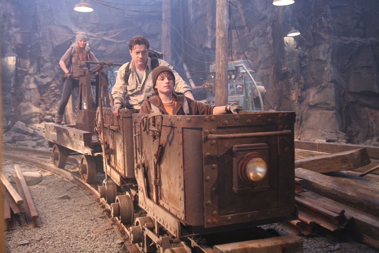
Mine car sequence
|
We
had many scenes with actors in a mine car
chase. Typically, the three actors (and
personal mine car) would be shot in their
own blue screen plates and then the three
plates would be choreographed and combined
in Maya. The actors would be standing on a
mine car on a motion base, but the bottom
chassis of the mine car would be missing and
had to be added as a set extension match
move. Set extension in stereo can be
complicated, since as soon as you translate
the projector image, the nature of the 2.5 D
cheat becomes apparent. So one of the three
mine cars (the most difficult to set extend)
becomes the master and the other mine cars
set extensions need be less exact.
|
|
|
The stereo trim of the camera is optimized
so that the most demanding mine car
projector looks correct in stereo.
The stereo mine car sequence was the most
complicated that we worked on and there are
many vital subtleties that I am leaving out.
Many object tracks were done in 3DE of a
rectangular mine car "chariot". These 3DE
solves were very good, but the point cloud
wasn't always perfectly perpendicular.
Normally we would have put lattices on the
mine car in Maya, but this would have broken
the kinematics of the pump and wheel
linkages of the mine car in Maya. So our
brilliant rigger Marc-Andre published
standard blend shapes, so that we could
deform the model without breaking the fk of
the chariot wheels.
Also, the animated motion of the mine car
was used as a path to procedurally extrude
the mine car rails, bridges and trestle.
|
|
Stereo rotoscoping
|
One
problem in stereoscopic vfx is creating roto
mattes that have the proper matching stereo
depth between the eyes. One possible
solution to this problem is to place a
texture card in the Maya scene and 3D
paint the rotoscope split line on the
texture card. Instead of rotoscoping the
bezier splines twice for the two eyes, you
only rotoscope the split once and use the
left/right Maya cameras to view the single
texture card at different perspectives. If
the texture card is placed at a suitable
depth in the Maya scene, then the stereo
rotoscoping would naturally blend smoothly
between left/right images.
|
|
Stereo viewing
|
There are several methods of
viewing in stereo.
In the vfx facility theater,
dual projectors with polarizers will be used
or a RealD system can be installed.
At the workstation, three
general methods are used:
- Anaglyph
- Shuttered
glasses
- Mirror
Anaglyph
uses red/green glasses and doesn't look
very good. But it has the advantage of
working with both CRT and LCD monitors.
3DE has a built in anaglyph function, as
does the Eric Gervais-Despres Maya stereo
camera.
Shuttered glasses only work with CRT work
station monitors, because of the lag of
LCD. Shuttered glasses are supported by
Framecycler. I didn't like the brand of
shuttered glasses that we used on JCE (too
dark and flickery), but I do like the
Crystal Eyes glasses that I'm now using.
An infrared transmitter sends the sync
information to the glasses. Framecycler
automatically loads stereo image sequences
which have the proper naming and padding
conventions for the left/right eyes.
My favorite method (although not
everyone's) is the mirror. A front surface
mirror (Edmund Scientific) is mounted in
front of the monitor, the glass almost
sideways to the viewer. Special renders of
the Playblast were produced where the left
eye was mirrored flipped in X (scale x=
-1) and placed to the left side of the
right playblast frame. The silvered part
of the mirror points to the left. The
artist puts her eye right up to the glass,
views the right image with the right naked
eye and the left (flopped) image through
the left eye, looking with the left eye at
the mirror.
This mirror technique can be hard to get
used to, but the quality of the image is
superb, once you train your eye with the
method. On Ant Bully, final composites for
Imax were all judged with this method. It
works with CRT and LCD. It works with
single or dual monitors. One problem wit
the mirror is that the user can
artificially fix slight convergence
problems, since the mirror can be rotated
by hand. On the other hand, polarizer and
shuttered glasses have projection
geometries that can't be cheated by the
viewer, so one always knows if the
convergence of the matchmove/comp is
correct.
In the past, I have worked with
photographers who were color blind,
although they succeeded professionally
anyway. Similarly, on JCE, we actually had
a couple of artists who could not see
stereoscopic properly. At the beginning,
we kept this a deep dark secret from
management, but in reality, even a one
eyed matchmove/layout artist can do stereo
work with little problem. They can easily
understand the problem intellectually and
produce great work. Stereo viewing is
always subjective and a certain supervisor
or director with the "reference eyes" will
be the ultimate judge of the stereo
effect.
|
|
Thanks to the Meteor JCE
stereo matchmove/ layout team:
|
Michael Archambault
Pierre Bonnette
Francis Camacho
Eric Desaulniers
Christian Emond
John Higbie
Daniel Lowenberg
Michael Karp
Muzaffer Korkut
Candida Nunez
Hernan Vietri
|

 |
|
 |