Distortion
in 3D Equalizer
Michael Karp
mckarp@aol.com
Oct 09, 2012
3DE, pfTrack, SynthEyes and Boujou all follow the same basic
Brownian model
https://en.wikipedia.org/wiki/Distortion_%28optics%29
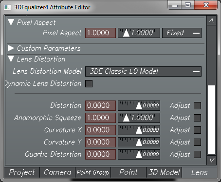
In 3DE, the Classic and the Radial Lens Distortion (LD) models are
almost the same.
The Distortion is actually a second order quadratic x 2. The degree 4
Quartic is fourth order x4
These gross parameters are identical in the two models. Type in some
values, you'll see.
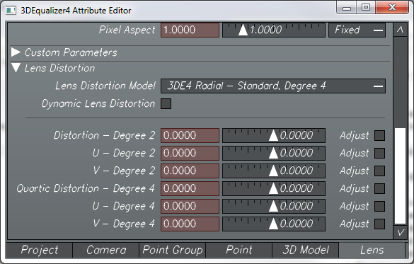
The difference between Classic and Radial is that the Radial
allows the distortion to be different on the left or right side of
the frame, asymmetrical. This is powerful, but can get you into
trouble with wild, implausible distortions. Often with a zoom
lens, LCO (Lens Centre Offset) is much more useful, especially for
stereo.
Second order adjusts the distortion across the entire frame.
Fourth order only adjusts the distortion at the edge of frame. So
if you are using a zoom lens with mustache distortion, where the
lens has positive distortion on one part (barrel distortion) and
negative distortion (pincushion) at another, then you will see an
S-curve of the distortion across the frame. By using e.g. positive
distortion for Degree 2 distortion and negative distortion for
Degree 4, you can get the lens grid to mustache S-curve like many
zoom lenses do.
When you click the Adjust buttons, it is usually best to not check
every button at one time. Start off with the Degree 2 and the
Degree 4, Adjust and then check that the undistort is plausible.
The F3 view will unwrap the image in real time OpenGL, so you can
see whether you are close. Then uncheck the Distortion 2 and the
Quartic and check the other three or four parameters, which are
fine tunes of the gross settings.
There are different strategies for determining lens distortion and
you can mix and match. Usually I start with a lens grid and a
matrix, determine rough distortion and then fine tune using th 2D
points that I've tracked for the final. You adjust the distortion
so that the Deviation error of the solve is lowest, while still
being plausible, i.e. the distortion is getting more rectilinear,
not less.
If there is only one valid straight edge in a plate, the Matrix
may or may not have enough data contained. But the totality of all
of the 2D points contains enough information to Calc a very useful
undistort.
The Brute Force is very slow, but it tries every single possible
combination, which can be more accurate. Adaptive is fast and
looks for "trends", but can choose implausible solutions and go
down the rabbit hole. Generally you don't want to Calc for more
than three parameters at a time.
If you have straight lines in the scene, then you can manually set
the gross second order distortion ahead of time and then use Fine
(not wide). This speeds things up and prevents the solver from
driving into a ditch with an implausible value. Fine means that
the parameter can't stray too far away from the correct value
suggested by the straight lines in the scene and saves time. But
if there are no straight lines in the plate/grid, then you
probably need to use Wide.
If a shot is fairly simple, don't waste time with LCO. But for stereo with a
zoom lens, the Radial model can get lost and create a very
different, asymmetrical distortion for left/right eyes, so LCO is
very good for zoom shots with tight LIDAR lineup needed.
So there are four methods for determining distortion, which can be
combined in a non-linear workflow:
-
Matrix, in F3, with the plate or a photographed
distortion grid
-
Manually adjusting the distortion in F3, with
the overlay grid, with the plate or a photographed
distortion grid
-
Parameter Adjustment window, which uses the 2D
tracks as the basis for distortion
-
F5, adjusting the
distortion and focal length value at the bottom of the view
port, while watching the "Hitchcock zoom" alignment of the
LIDAR.
Of course with the new
Lineup window, you should even need to check anything in Maya,
fine alignment should be visible in 3DE F5. Notice that for a
dense LIDAR, 3DE has the very useful hidden line removal, not
generally available in Maya, unless you use the Mental Ray
Contour function for software render.
Also, the Anamorphic Squeeze parameter has nothing to do with a
Cinemascope/Panavision lens with a non square pixel aspect ratio
of two. So this value on a spherical or anamorphic lens will
often be around 1.
FYI, here are the distortion parameters available in the big
four tracking softwares. 3DE has the largest number of
adjustments, although with great power comes great
responsibility, i.e. the extra parameters are very useful for
difficult shots, but can be confusing.
-
3DE: degree 2, degree 4, plus three or
four trims
-
pfTrack: degree 2, degree 4, plus
anamorphic squeeze (very different than anamorphic)
-
SynthEyes: degree 2
-
Boujou:
degree 2, LCO
All have LCO
adjustments as well.
Theoretically the Brownian/Newton values in 3DE and pfTrack
should be the same, but they do not give identical values. So
pfTrack needs the pfBarrel node in Nuke and 3DE needs the
WETA/3DE undistort node in Nuke. There is also a SynthEyes undistort
node available for Nuke.
Shooting grids
The angled
"Modern" grid will determine focal length, but it typically
has a high deviation error.
So the "Classic" straight grid is often better, according to
Rolf.
In the old days before the Matrix, the grid would need to be
positioned exactly parallel to the camera, which is almost
impossible to do in practice, outside a laboratory.
But with a "straight" Matrix, theoretically the grid can be
keystoned slightly away from parallel and still give great
results, much better and easier than the old fashioned
traditional grid, without a Matrix. But again, only an angled
grid will determine focal length.
But for focal length, there are other issues. An angled Matrix
shot will require the grid to be placed very close to the
camera and the focus setting will be wrong. A plate is usually
shot at about ten feet away, but because the printed grid is
small, the grid shot usually has to be focused at a distance
of about 2 feet. Thus, the calculated FOV is off slightly,
because of lens breathing. So I like to stop the camera down
to t/16, focus at the "correct" 10 foot distance and let depth
of field keep the image sharp. And with an angled grid, there
are often checkerboard squares that aren't even covered at the
edge of frame, or are too small or out of focus to Matrix
accurately.
The other methods of determining focal length still work. If
you have accurate LIDAR in F5 Lineup, you can "Hitchcock zoom"
the focal length and low order distortion. Or you can do a
Fine Adjust of focal length, etc., in the Parameter Adjustment
window, as always.